Industrial API Trunnion Mouted Fixed Type Ball Valve Manufacturer Price factory china

What's Trunnion ball valves?
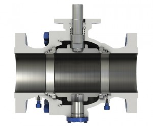
A trunnion ball valve means that the ball is constrained by bearings and is only allowed to rotate, the majority of the hydraulic load is supported by the System constraints, resulting in low bearing pressure and no shaft fatigue.
The ball valve is a form of quarter-turn valve which uses a hollow, perforated and fixed/supported ball to control flow through it.
The pipeline pressure drives the upstream seat against the stationary ball so that the line pressure forces the upstream seat onto the ball causing it to seal. The mechanical anchoring of the ball absorbs the thrust from the line pressure, preventing excess friction between the ball and seats, so even at full rated working pressure operating torque remains low. This is particularly advantageous when the ball valve is actuated because it reduces the size of the actuator and hence the overall costs of the valve actuation package. The trunnion is available for all sizes and for all pressure classes but they are mainly for large sizes and high pressure conditions
Main features of NORTECH Trunnion ball valves
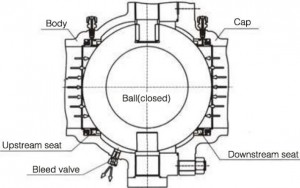
1.Double Block and Bleed(DBB)
When the valve is closed and the middle cavity is emptied through the discharge valve, the upstream and downstream seats will independently block. Another function of the discharge device is that the valve seat can be checked if there is a leakage during the test. In addition, the deposits inside the body can be washed through the discharge device.the discharge device is designed to reduce damage to the seat by impurities in the medium.
2.Low Operating Torque
The trunnion pipeline ball valve adopts the trunnion ball structure and floating valve seat, so as to achieve lower torque under operating pressure. It uses self- lubricating PTFE and metal sliding bearing to reduce the friction coefficient to the lowest in conjunction with the high intensity and high fineness stem
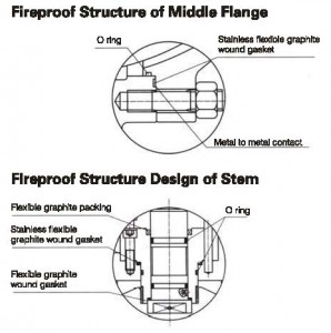
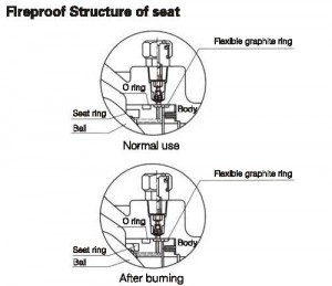
4.Fireproof Structure Design
In case of fire during the use of valve, the seat ring, stem O ring and middle flange O ring made of PTFE,rubber of other non-metal materials will be decomposed or damaged under high temperature.Under pressure of the medium, the ball valve will push the seat retainer rapidly towards the ball to make the metal seal ring contact the ball and form the auxiliary metal to metal sealing structure,which can effectively control valve leakage.The fireproof structure design of trunnion pipeline ball valve conforms to requirements in API 607,API 6FA,BS 6755 and other standards.
5.Anti-static Structure
The ball valve is designed with the anti- static structure and adopts the static electricity discharge device to directly form a static channel between the ball and body through the stem,so as to discharge the static electricity produced due to friction during the opening and closing of ball and seat through the pipeline,avoiding fire of explosion that may be caused by static spark and ensuring system safety.
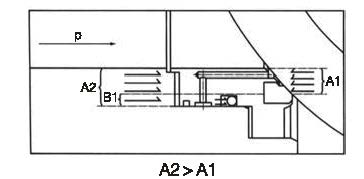
7.Single Sealing
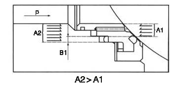
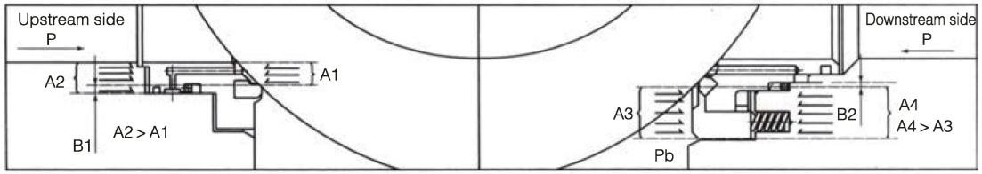
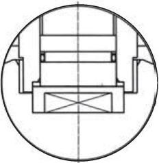
(Automatic Pressure Relief in Middle Cavity of Valve) Generally,the single sealing structure is used.That is,there is only the upstream sealing. As the independent spring loaded upstream and downstream sealing seats are used, the over-pressure inside valve cavity can overcome the pre- tightening effect of the spring,so as to make the seat released from the ball and realize automatic pressure relief towards the downstream part.The upstream side: When the seat moves axially along the valve,the pressure “P” exerted on the upstream part (inlet) produces a reverse force on A1, As A2 is higher than A1, A2-A1=B1,the force on B1 will push the seat to the ball and realize tight sealing of the upstream part
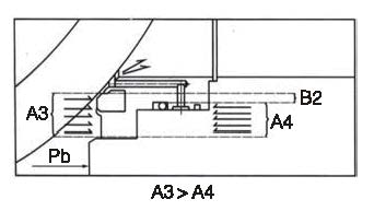
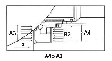
The downstream side: Once the pressure “Pb” inside the valve Cavity increases, the force exerted on A3 is higher than that on A4. As A3-A4=B2, the pressure differential on B2 will overcome the spring force to make the seat released from the ball and realize pressure relief of valve cavity to the downstream part afterwards,the seat and ball will be sealed again under the spring action.
Secondary sealing: Downstream.
When the pressure differential is lower or there is no pressure differential,the floating seat will move axially along the valve under the spring action and push the seat towards the ball to keep tight sealing. When the valve cavity pressure P increases,the force exerted on the area A4 of valve seat in higher than the force exerted on the area A3,A4- A3=B1.Therefore,the force on B1 will push the seat towards the ball and realize tight sealing of the upstream part.
9.Safety Relief Device
As the ball valve is designed with the advanced primary and secondary sealing that has double piston effect,and the middle cavity cannot realize automatic pressure relief, the safety relief valve must be installed on the body in order to prevent the danger of over-pressure damage inside the valve cavity that may occur due to thermal expansion of medium.The connection of the safety relief valve is generally NPT 1/2. Another point to be noted is that the medium of the safety relief valve is directly discharged into the atmosphere. In case direct discharging into the atmosphere is not allowed, we suggest that the ball valve with a special structure of automatic pressure relief towards upper stream should be used.Refer to the following for details. Please indicate it in the order if you do not need the safety relief valve or if you would like to use the ball valve with the special structure of automatic pressure relief towards upper stream.
10.Special Structure of Automatic Pressure Relief Towards Upper Stream
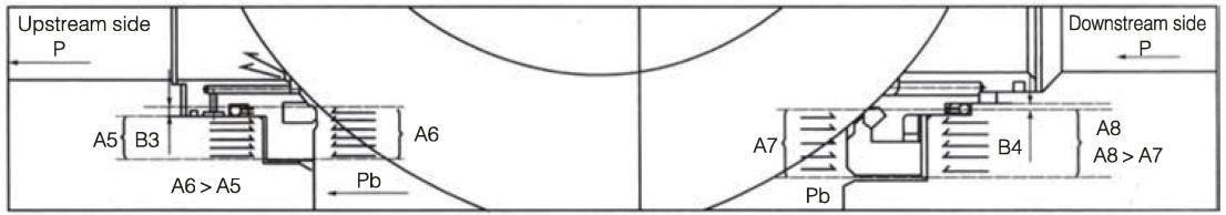
As the ball valve is designed with the advanced primary and secondary sealing that has double piston effect,and the middle cavity cannot realize automatic pressure relief, he ball valve ith the special structure is recommended to meet the requirements of automatic pressure relief and ensure no pollution to the environment.In the structure,the upper stream adopts primary sealing and the lower stream adopts primary and secondary sealing When the ball valve is closed,the pressure in the valve cavity can realize automatic pressure relief to the upper stream,so as to avoid the danger caused by cavity pressure.When the primary seat is damaged and leaks,the secondary seat can also play the function of sealing.But special attention shall be paid to the flow direction of the ball valve.During the installation.Note the upstream and downstream directions.Refer to the following drawings for sealing principle of the valve with the special structure
Principle drawing of ball valve upstream and downstream sealing
Principle drawing of ball valve cavity pressure relief to the upper stream and down stream sealing
12.Corrosion Resistance and Sulfide Stress Resistance
Certain corrosion allowance is left for the body wall thickness.
The carbon steel stem,fixed shaft,ball,seat and seat ring are subjected to chemical nickel plating according to ASTM B733 and B656.In addition,various corrosion resistant materials are available for users to select.According to customer’s requirements,the valve materials can be selected according to NACE MR 0175 / ISO 15156 or NACE MR 0103,and strict quality control and quality inspection should be carried out during the manufacturing so as to fully meet the requirements in the standards and meet the service conditions in sulfurization environment
Blow-out Proof Stem
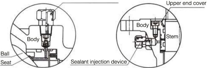
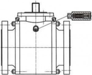
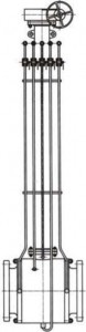
13.Extension Stem
As for the embedded valve,the extension stem can be supplied if ground operation is required.The extension stem is composed of stem, sealant injection valve,and drainage valve that can be extended to the top for the convenience of operation. Users should indicate the extension stem requirements and length when placing orders. For ball valve driven through electric,pneumatic and pneumatic – hydraulic actuators,the extension stem length should be from the center of pipeline to top flange.
Schematic diagram of extension stem
Specifications of NORTECH Trunnion ball valves
Trunnion Ball Valve Technical Specifications
|
Nominal diameter |
2”-56”(DN50-DN1400) |
|
Connection Type |
RF/BW/RTJ |
|
Design standard |
API 6D/ASME B16.34/API608/MSS SP-72 ball valve |
|
Body material |
Cast steel/Forged steel/Cast stainless steel/Forged stainless steel |
|
Ball material |
A105+ENP/F304/F316/F304L/F316L |
|
Seat material |
PTFE/PPL/NYLON/PEEK |
|
Working temperature |
Up to 120°C for PTFE |
|
|
Up to 250°C for PPL/PEEK |
|
|
Up to 80°C for NYLON |
|
Flange end |
ASME B16.5 RF/RTJ |
|
BW end |
ASME B 16.25 |
|
Face to face |
ASME B 16.10 |
|
Pressure temperaure |
ASME B 16.34 |
|
Fire safe&anti-static |
API 607/API 6FA |
|
Inspection standard |
API598/EN12266/ISO5208 |
|
Exposion proof |
ATEX |
|
Type of operation |
Manual gearbox/Pneumatic actuator/Electric actuator |
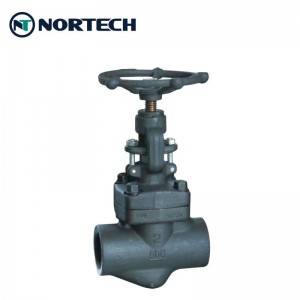
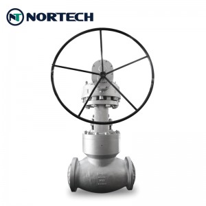
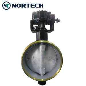
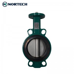
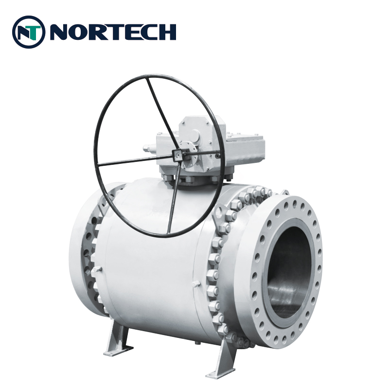
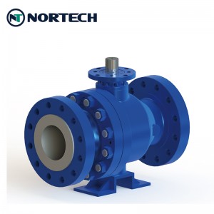
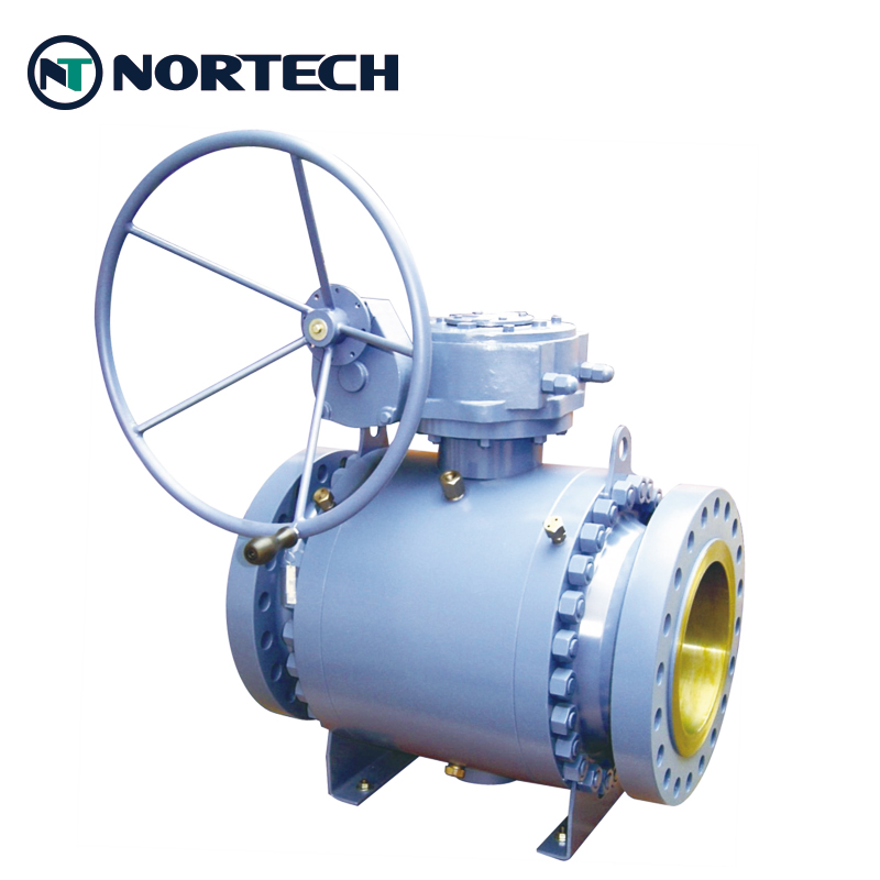
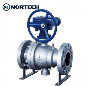
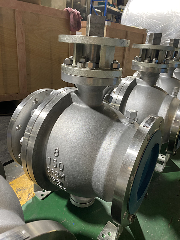
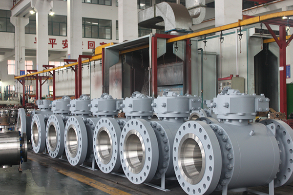
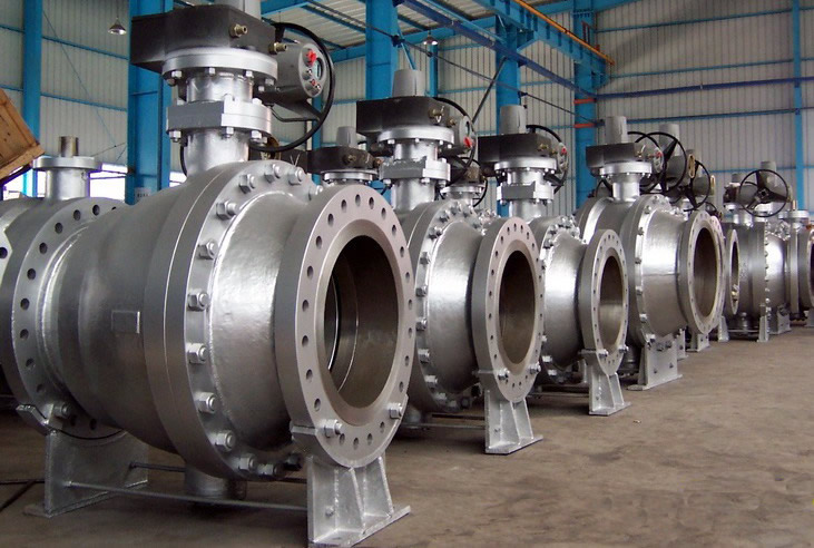
Product Show:
Application of NORTECH Trunnion ball valves
This kind of Trunnion Ball Valve is widely utilized in the exploiting, refining and transporting system of oil, gas and mineral. It can be also utilized to produce chemical products, medicine; production system of hydroelectricity, thermal power and nuclear power; draining system,