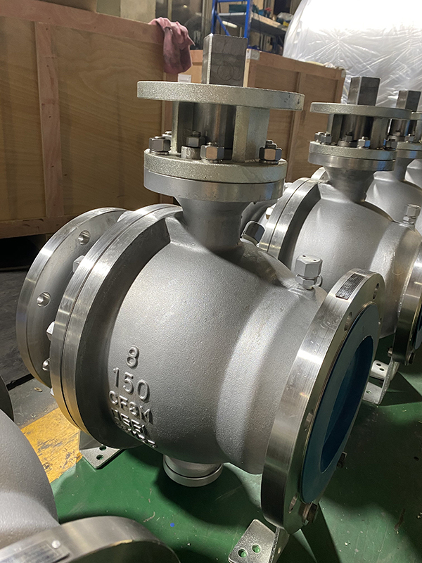
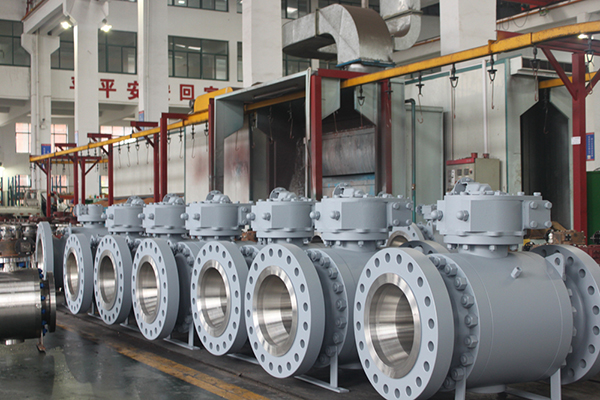
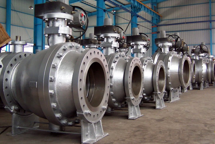
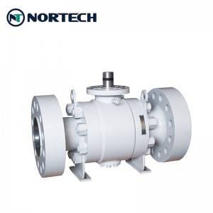
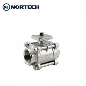
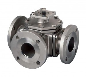
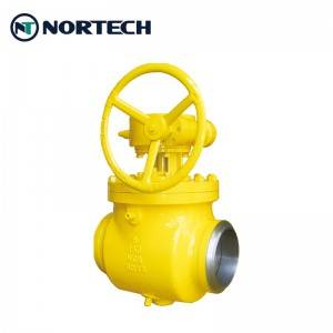
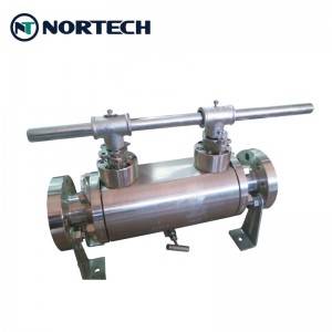
Trunnion mounted Ball Valve
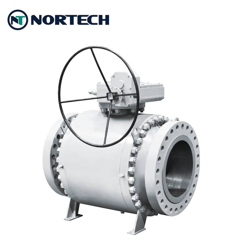
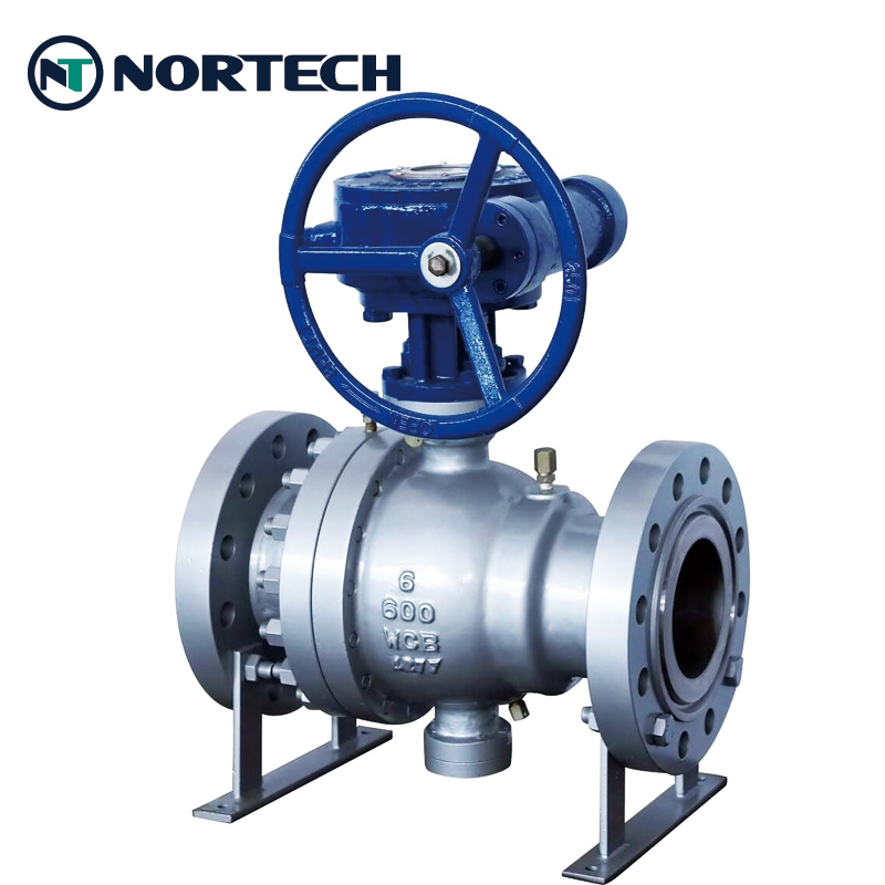

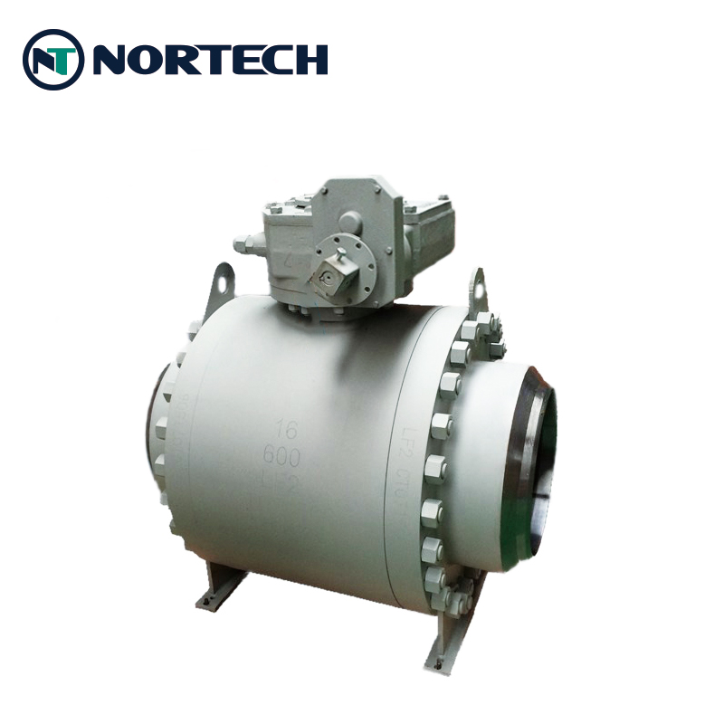
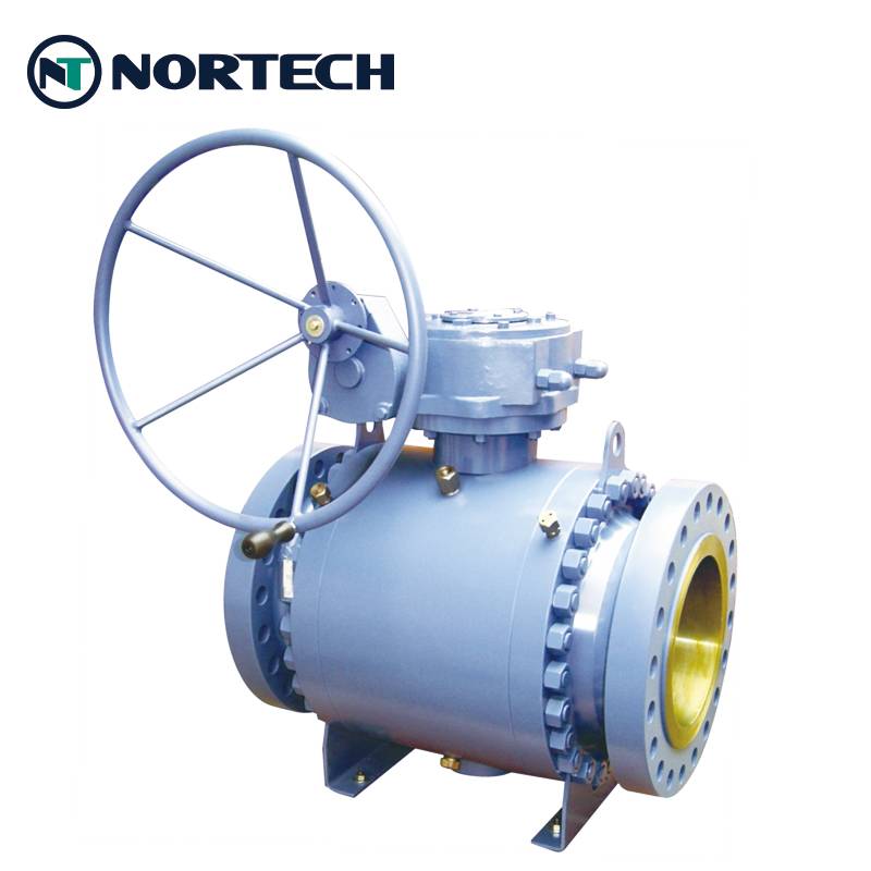
A trunnion mounted ball valve is a quarter-turn valve that uses a hollow, perforated ball — fixed and supported top and bottom by bearings (trunnions) — to control flow through the line. Because the ball is constrained by the bearings and only rotates in place, the majority of the hydraulic load is carried by the system constraints rather than the stem, resulting in low bearing pressure and no shaft fatigue.
This design delivers low operating torque, easy operation, and minimized seat wear: isolating the stem and ball prevents side loading and protects the downstream seats, improving performance and service life. A separate spring mechanism combined with upstream line pressure provides superior sealing at both low and high pressures. Manufactured to API 6D and ASME B16.34, with API 607 fire-safe and ATEX certification, the valve is well suited to high-pressure and sour-service applications compliant with NACE MR0175.
In operation, pipeline pressure drives the upstream seat against the stationary ball, forcing it to seal. The mechanical anchoring of the ball absorbs the thrust from line pressure, preventing excess friction between ball and seats, so operating torque remains low even at full rated working pressure. This is particularly advantageous for actuated valves, as it reduces actuator size and the overall cost of the actuation package.
Trunnion mounted ball valves are available in all sizes and pressure classes, but are mainly specified for large sizes and high-pressure conditions. Standard range NPS 2″–56″, Class 150–2500.
Trunnion Mounted Design — the ball is mechanically anchored by upper and lower bearings, absorbing line-pressure thrust so bearing loads stay low and operating torque remains low even at full rated pressure, reducing actuator size and total cost of ownership.
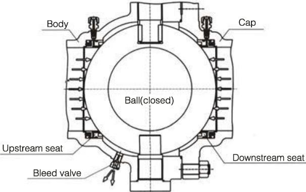
When the valve is closed and the central cavity is drained through the bleed valve, the upstream and downstream seats block independently. The bleed device also allows the seats to be checked for leakage during testing and lets deposits inside the body be flushed out, reducing seat damage caused by impurities in the medium.
The trunnion-mounted ball and floating-seat design achieves low torque under operating pressure. Self-lubricating PTFE and metal sliding bearings, combined with a high-strength, finely finished stem, keep the friction coefficient to a minimum.
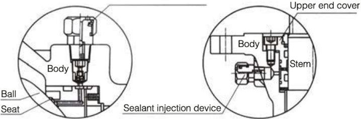
Valves of 6″ (DN150) and above are fitted with sealant injection fittings on the stem and seats. If a seat ring or stem O-ring is damaged in service, sealant can be injected to stop leakage at the seat ring or stem. Where necessary, the auxiliary sealing system can also flush and lubricate the seat to keep it clean.
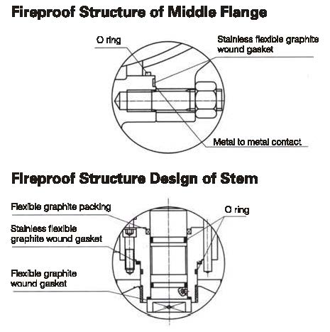
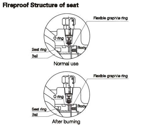
If a fire occurs, the PTFE, rubber or other non-metal seat rings, stem O-ring and middle-flange O-ring may decompose or fail at high temperature. Under medium pressure the valve then drives the seat retainer rapidly against the ball, so the metal sealing ring contacts the ball and forms a secondary metal-to-metal seal that effectively limits leakage. The fire-safe design complies with API 607, API 6FA, BS 6755 and other standards.
An anti-static design with a static-discharge device creates a conductive path between the ball, stem and body. Static electricity generated by friction during opening and closing is discharged to the pipeline, preventing fire or explosion from static sparks and ensuring system safety.
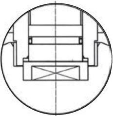
The stem uses a blow-out-proof design. A step at the bottom of the stem, together with the upper end cover and screws, retains the stem so it cannot be ejected by the medium even under an abnormal pressure rise in the valve cavity.
A corrosion allowance is included in the body wall thickness. The carbon-steel stem, trunnion, ball, seat and seat ring are electroless-nickel plated to ASTM B733 and B656, and a wide range of corrosion-resistant materials is available. On request, materials can be selected to NACE MR0175 / ISO 15156 or NACE MR0103, with strict quality control to meet sour (sulfide) service conditions.
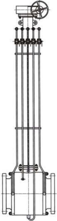
For buried valves requiring above-ground operation, an extension stem can be supplied. It combines the stem, sealant injection valve and drain valve, extended to the surface for convenient operation. Please specify the extension stem requirement and length when ordering. For electric, pneumatic or pneumatic-hydraulic actuated valves, the extension length is measured from the pipeline centerline to the top flange.
Sealing is achieved by two floating seat retainers that move axially to block the fluid, providing both ball sealing and body sealing. Low-pressure sealing is provided by spring pre-tension, while a properly designed seat piston effect provides high-pressure sealing using the medium pressure itself. Two sealing modes are available, described below.
Generally a single-seal (upstream-only) arrangement is used. Because the upstream and downstream seats are independently spring-loaded, over-pressure inside the valve cavity overcomes the spring pre-load, releasing the seat from the ball and automatically relieving cavity pressure to the downstream side.
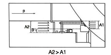
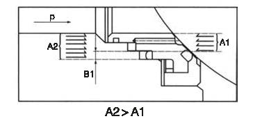
Upstream: as the seat moves axially, the inlet pressure P acts on areas A1 and A2; since A2 is larger than A1 (A2−A1=B1), the net force on B1 pushes the seat against the ball for tight upstream sealing.
Downstream: when cavity pressure Pb rises, the force on A3 exceeds that on A4 (A3−A4=B2); the differential on B2 overcomes the spring force, releasing the seat to relieve cavity pressure downstream. The spring then reseats the seat against the ball.
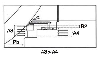
For special service conditions, a double-seal (double-piston) structure can be provided on both sides of the ball. Under normal conditions the primary seal operates; if the primary seat is damaged and leaks, the secondary seat maintains sealing for added reliability. The combined seat uses a metal-to-metal primary seal and an FKM (fluorine rubber) O-ring secondary seal to achieve bubble-tight sealing. At low or zero differential pressure the spring presses the seat against the ball; as differential pressure rises, the sealing force between seat, body and ball increases for tighter sealing.
Primary seal (upstream): at low or zero differential pressure the floating seat moves axially under spring force against the ball. The net force on B1 (A2−A1=B1) pushes the seat toward the ball for tight upstream sealing.
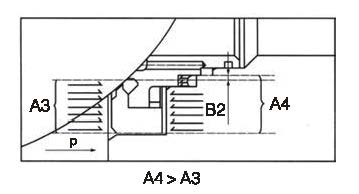
Secondary seal (downstream): as cavity pressure P rises, the force on area A4 exceeds that on A3 (A4−A3=B2); the force on B2 drives the seat against the ball to maintain downstream sealing.
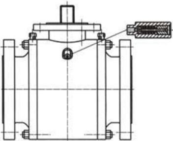
Because the primary/secondary double-piston design means the central cavity cannot self-relieve, a safety relief valve must be fitted to the body to prevent over-pressure damage from thermal expansion of the trapped medium. The relief valve connection is normally NPT ½, discharging directly to atmosphere. Where discharge to atmosphere is not permitted, we recommend the special structure with automatic pressure relief to the upstream side (below). Please state on the order if the safety relief valve is not required, or if the automatic-relief structure is preferred.
Where the double-piston design prevents cavity self-relief, this structure provides automatic relief without environmental discharge. The upstream side uses a primary seal; the downstream side uses primary and secondary seals. When the valve is closed, cavity pressure relieves automatically to the upstream side, avoiding the hazard of trapped cavity pressure; if the primary seat is damaged and leaks, the secondary seat still seals. Note the valve is flow-directional — observe the upstream/downstream orientation during installation. See the diagrams for the sealing principle.


| Design standard | API 6D / ASME B16.34 / API 608 / MSS SP-72 |
| Size range | 2″–56″ (DN50–DN1400) |
| Pressure rating | ASME Class 150–2500 |
| Connection type | RF / BW / RTJ |
| Flange end | ASME B16.5 RF / RTJ |
| BW end | ASME B16.25 |
| Face to face | ASME B16.10 |
| Pressure-temperature rating | ASME B16.34 |
| Fire-safe & anti-static | API 607 / API 6FA |
| Inspection standard | API 598 / EN 12266 / ISO 5208 |
| Explosion proof | ATEX |
| Operation | Manual gearbox / Pneumatic / Electric actuator |
| Body | Cast steel / Forged steel / Cast stainless steel / Forged stainless steel |
| Ball | A105+ENP / F304 / F316 / F304L / F316L |
| Seat | PTFE / PPL / Nylon / PEEK |
| Working temperature | PTFE: up to 120°C PPL / PEEK: up to 250°C Nylon: up to 80°C |
NORTECH trunnion mounted ball valves are widely used for isolation and on/off control in the production, refining and transmission of oil, gas and minerals. They also serve chemical and pharmaceutical processing, power generation, and water and drainage systems where reliable bi-directional sealing under high pressure is essential.